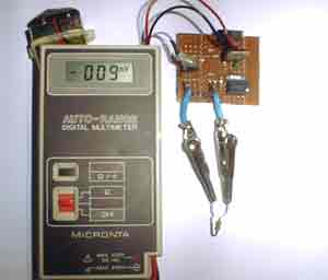
I needed a way to measure hand-wound RF inductors in my second lab, and since I would only be doing this occasionally, I didn’t need anything fancy, and since once a friend finishes his AT90S1200-based design, I plan to make one myself, I figured I’d use this for less than a year, so I didn’t want to invest a lot of time in making it . I had run across the forerunner of this circuit, one that is more sophisticated in that it has a zero adjustment and range switch, but it was limited to higher inductances. I adapted it to the components I had on hand and changed it so that it would work in the 500 nanohenry to 50 microhenry range.The original circuit was reportedly published a few years ago by the Amrican Radio Relay League, so it is with appreciation of the ARRL that I make this circuit available (Wouff Hong members: dit dit dit dit….dit dit).
The circuit’s operating principle is that if you make a pulse width proportioal to inductance, and keep the pulse frequency and amplitude constant, and then pass the pulse through a low pass filter so that only the average voltage comes out, the resulting DC voltage is proportional to the inductance.
Stated another way:
Pulse width = Inductance X some constant
DC out = Pulse width X Pulse Ampltude X Freqency
Where DC out and Pulse Amplitude is in volts, and Pulse width is in seconds and pulse frequency is in Hz (1/seconds).
The pulse frequency is set by a schmitt trigger oscillator composed of a feedback resistance (2k pot and 3.9k fixed resistor). a 1000 pf capacitor to ground, and a schmitt trigger. The hysteresis in the schmitt trigger allows it to oscillate with the simple feedback circuit. The pulse width that is proportional to the inductance is made by drving the unknown inductance through a resistor and connecting the resultant sawtooth waveform to the input of another schmitt trigger which, because of the sharp switching action on its output that results from its hysteresis, provides a nice rectangualr pulse. The pulse width is proportional to the inductance and inversely proportional to the resistance. In order to get a pulse with a width that is substantiall longer than the rise and fall time of the schmitt trigger, whcih is a requiremnt for good linearity, while the inductance was in the 500 nH range, I had to use a very low resistance, hence the three 330 ohm resistors and their drivers in parallel. The last inverter in merely to make the pulse positive in polarity so that the voltage increases as the inductance increases.
This circuit is only accurate for broadband inductors. Inductors with iron cores, high permeability ferrites, or with large amonts of shunt capacitance cannot be measured accurately.
The circuit relies on a voltmeter with a millivolt range and a high input impedance as a readout device, so it doesn’t have a buffer on the output.
For more detail: RF Inductance Meter using microcontroller

