Summary of Running TX433 and RX433 RF modules with AVR microcontrollers
This article describes building a wireless communication system between two AVR microcontrollers using TX433 and RX433 RF modules. It covers hardware setup, including power requirements and antenna usage, and details a software strategy using 4-byte data packages with synchronization, addressing, data, and checksum bytes to ensure reliable transmission over the air.
Parts used in the Wireless Communication System:
- TX433 RF Transmitter Module
- RX433 RF Receiver Module
- Atmega8 Microcontroller
- 30 – 35cm Antennas
Sometimes in embedded design you may want to go wireless. Might be you will want to log various readings of remotely placed sensors, or simply build a remote control for robot or car alarm system.
Radio communications between two AVR microcontrollers can be easy when specialized modules are used. Lets try to run very well known RF modules TX433 and RX433 that (or similar) can be found almost in every electronics shop and pair of them cost about ~15 bucks.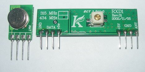
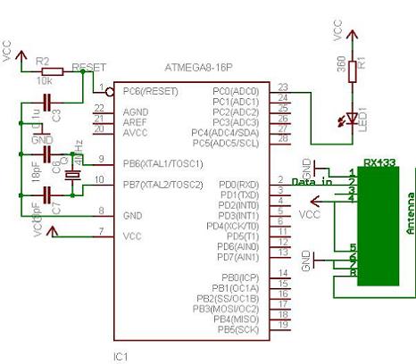
Transmitter and receiver modules are tuned to work correctly at 433.92MHz. Transmitter can be powered from 3 to 12V power supply while receiver accepts 5V. 5V is common for AVR microcontrollers so no problems with interfacing. Modules don’t require addition components – just apply power and connect single data line to send information to/from and that’s it. For better distances apply 30 – 35cm antennas. Modules use Amplitude-Shift Keying(ASK) modulation method and uses 1MHz bandwidth.
I have constructed two separate circuits for testing on Atmega8 microcontrollers.
Transmitter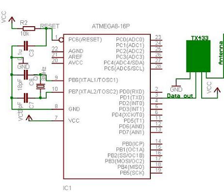
Receiver
Lets move on to software part. Radio transmission is a bit more complicated than wired communications because you never know what radio signals are present on air. So all matters how transmitted signal is encoded. And this is a part where you have many choices: use hardware encoding like USART or write your own based on one of many ending methods like NRZ, Manchester etc. In my example I have used AVR USART module to form data packs. Using hardware encoders solves many problems like synchronization, start and stop, various signal checks. But as long as I was practising you cannot rely on plain USART signal. Here you can actually improvize by adding various checks and so on.
I decided to form 4 byte data packages in order to send one byte information. These include:
- one dummy synchronization byte (10101010);
- one address byte – in case there are more receivers(or transmitters);
- one data byte;
- and checksum which is actually a sum of address and data(address+data).
Why did I use a dummy byte at the beginning of package. Simply I noticed, that when transmitter doesn’t transmit any data – receiver catches various noises that come from power supply or other sources because receiver likes adjust its input gain depending on input signal level. First byte tunes receiver to accept normal signal after then address byte, data and checksum can be read more reliably. Probably with different transmission modules you may exclude this dummy byte.
For more detail: Running TX433 and RX433 RF modules with AVR microcontrollers
- How much do the TX433 and RX433 modules cost?
A pair of these modules costs about ~15 bucks. - What voltage powers the transmitter module?
The transmitter can be powered from a 3 to 12V power supply. - What voltage does the receiver module require?
The receiver accepts 5V. - What modulation method do these modules use?
Modules use Amplitude-Shift Keying or ASK modulation method. - Why is a dummy synchronization byte included in the data package?
The first byte tunes the receiver to accept normal signals after it catches noise from power supplies or other sources. - What components make up the 4-byte data package?
The package includes one dummy synchronization byte, one address byte, one data byte, and a checksum. - How is the checksum calculated in this project?
The checksum is actually a sum of the address and data bytes. - Can plain USART signals be relied upon for radio transmission?
You cannot rely on plain USART signal because radio signals are complicated and require additional checks.