
Summary of 8051 ADC0808 LCD DISPLAY VOLTMETER
This article describes using the ADC0808 8-channel analog-to-digital converter with an 8051 microcontroller to build an LCD-display voltmeter. It explains ADC0808 inputs IN0–IN7, 8-bit outputs OUT0–OUT7, 3-bit address lines A, B, C for channel selection, required clock frequency (10 kHz–1.28 MHz), VREF+ and VREF- usage, and control signals Start, OE, and EOC. Project files including Keil source code and Proteus ISIS simulation are provided.
Parts used in the 8051 ADC0808 Lcd Display Voltmeter:
- ADC0808 analog-to-digital converter
- 8051 microcontroller
- LCD display
- Analog input source(s) (IN0–IN7)
- Clock source for ADC0808 (10 kHz–1.28 MHz)
- VREF+ and VREF- connections/reference
- Control signal wiring for Start, OE, and EOC
- Power supply
- Connecting wires and PCB or prototyping board
ADC0808 analog / digital converter of the 8 analog inputs (IN0-IN7) and 8-bit digital output (OUT0-OUT7) are available. Entries will be transferred to the digital output of the converter which converted to 3-bit ADD,…Electronics Projects, 8051 ADC0808 Lcd Display Voltmeter “8051 example, avr project, keil example, microcontroller projects, “
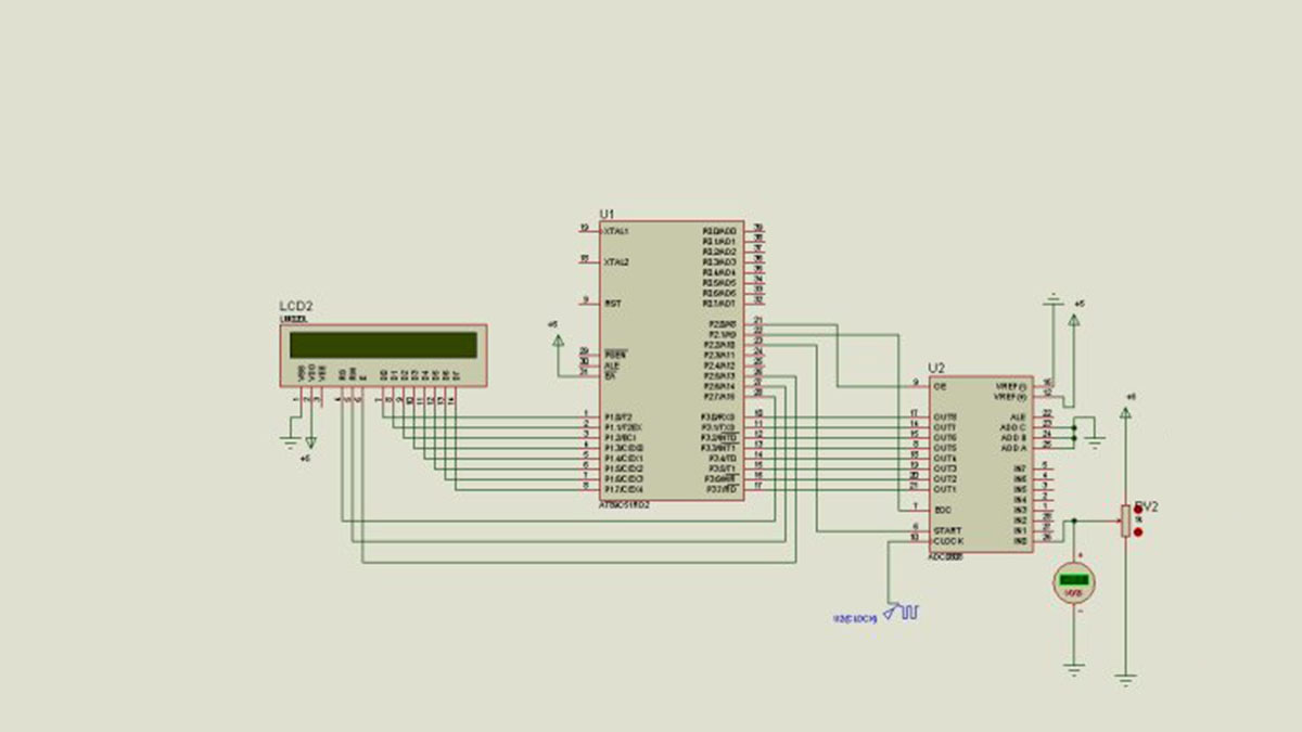
ADC0808 analog / digital converter of the 8 analog inputs (IN0-IN7) and 8-bit digital output (OUT0-OUT7) are available. Entries will be transferred to the digital output of the converter which converted to 3-bit ADD, ADD B, and C address ADD is decided according to the tips. ADC0808 to run the ADC clock (Clock) at the end of about 10 KHz-1280 KHz frequency values of the hour mark, which should be applied. VREF (+) terminal of the maximum amplitude of the analog signal to be sampled Vref (-) to indicate the minimum value of the signal to be sampled is used for. Applications Vref (-) usually bağlanır.start soil, OE (Output Enable) and the EOC (End of Conversion) are end-end control of the ADC0808.
8051 VOLTMETER SCHEMATIC
Source: https://320volt.com/en/8051-ile-a-d-ceviricili-lcd-gostergeli-voltmetre/ ADC0808 8051 Lcd Display Voltmeter keil source code and proteus isis simulation files: 8051-adc0808-lcd-display-voltmeter.rar
- How many analog inputs does the ADC0808 provide?
The ADC0808 provides 8 analog inputs labeled IN0 to IN7. - What digital output size does the ADC0808 produce?
The ADC0808 produces an 8-bit digital output on OUT0 to OUT7. - How are analog channels selected on the ADC0808?
Channels are selected using 3-bit address lines A, B, and C. - What clock frequency should be applied to the ADC0808?
The ADC0808 clock should be in the range of about 10 kHz to 1.28 MHz. - What are VREF+ and VREF- used for?
VREF+ sets the maximum amplitude and VREF- sets the minimum amplitude of the analog signal to be sampled. - Which control signals manage ADC0808 operation?
Start, OE (Output Enable), and EOC (End of Conversion) control the ADC0808 operation. - Is source code and simulation available for this project?
Yes; Keil source code and Proteus ISIS simulation files are provided in the referenced archive. - Can the ADC0808 outputs be read directly by the 8051?
Yes; the ADC0808 outputs are digital (OUT0–OUT7) and can be read by the 8051 when OE is enabled.
