
Summary of Obstacle Avoiding Robot using AVR ATmega32 – Part II
This article details the construction of an infrared (IR) reflectance sensor system for an obstacle-avoiding robot. It explains that the sensor uses an IR LED transmitter and a receiver to detect obstacles by measuring reflected light. The system requires three such elements mounted at the front, utilizing specific resistor values (150Ω and 22KΩ). The output voltage varies between 0V and 5V based on obstacle proximity and is converted into a 10-bit digital value (0–1024) by an AVR MCU's Analog-to-Digital Converter for processing.
Parts used in the Obstacle Avoiding Robot:
- IR Transmitter (IR LED)
- IR Receiver
- Resistor R1 (150 ohms)
- Resistor R2 (22K ohms)
- AVR MCU with ADC
Hello and Welcome back to the second part of Obstacle Avoiding Robot Tutorial. In the last part we studied the drive system and the mechanical construction of our robot. In this part we will make the sensor part. The sensors will help our robot detect obstacle in its path. The sensor system is of very basic type of infrared(IR) reflectance sensor. It is made up of an IR Transmitter and an IR receiver. The IR transmitter is an IR LED which emits light in IR spectrum that is invisible to human eye. The IR receiver can detect those rays.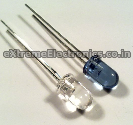
A Matching Pair of IR Rx and Tx, The Blue One is Tx (LED).
The IR Sensor Element
The IR Sensor element is made up of an IR Tx,IR Rx and few resistors. The schematic is given below. We need three such elements mounted in front of the robot to sense obstacles in front of it.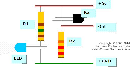
IR Reflectance sensor schematic. |
As you can see the sensor element has two pins for power supply and an Output pin. The output is a variable voltage between 0 and 5v depending on the type and distance of the obstacle. It tends to 5v as some obstacle comes near it
IR Sensor Construction Guidelines.
The value of R1 is 150 ohms and R2 is 22K. The color code is visible in the image above. The values are very critical so please use only the specified values. Also note that the Rx which is BLACK in color (some times transparent glass like also) has its small leg connected to the positive supply, its NOT an error, so connect it exactly that way only.
The IR Rx and Tx should be mounted in such a way that the IR rays from Tx falls on the Obstacle and Return back and hit the Rx.
The output of the Sensor element is fed to the Analog To Digital Converter of AVR MCU. The ADC of avr will convert the output to a 10bit digital value which ranges from 0-1024. Thus you can read the ADC to check if the sensor has some obstacle in front of it. Reading ADC is simple in xBoard v2.0 and is documented in details in this tutorial.
For more detail: Obstacle Avoiding Robot using AVR ATmega32 – Part II
- What components make up the IR sensor element?
The sensor element consists of an IR transmitter, an IR receiver, and a few resistors. - How many sensor elements are needed for the robot?
You need three such elements mounted in front of the robot to sense obstacles. - What are the specific values for resistors R1 and R2?
R1 must be 150 ohms and R2 must be 22K ohms. - How does the output voltage behave when an obstacle approaches?
The output voltage tends toward 5V as an obstacle comes near the sensor. - How does the MCU process the sensor signal?
The ADC converts the variable voltage output into a 10-bit digital value ranging from 0 to 1024. - Which leg of the black IR receiver connects to the positive supply?
The small leg of the black IR receiver connects to the positive supply. - Can humans see the light emitted by the IR transmitter?
No, the IR LED emits light in the IR spectrum which is invisible to the human eye.
