With a single LED you can indicate the state of something: on or off. That might be a little boring. With an array of LEDs you can display characters or even some simple blocky graphics. That might add a little pizzaz to a small microcontroller project.
You could use individual LEDs wired into a grid of rows and columns, or you can make use of a module that has the LEDs conveniently placed into a single package. Who wants to wrangle with a pile of LEDs? That is a LOT of leads to solder.
Remember the old dot-matrix printers? CGA displays? No? Well old dudes like myself sure do. Many devices like those displayed or printed their characters as an array of 7 rows of 5 pixels/dots. This project will help you learn how to use a 5 by 7 LED array.
As an alternate you can make use of an 8 by 8 LED array.
This Instructable will cover how the LED Array Module works and how to design a character set to display. I will put together a very simple microcontroller circuit to drive the display, and list the development environment and some of the firmware needed to do the task.
Step 1 An array of LEDs
“Encoding column patterns” sounds like something an android would do as a leisure activity. For this Instructable it is converting a pattern of illuminated LEDs into a hex value that can be used in the microcontroller source code.
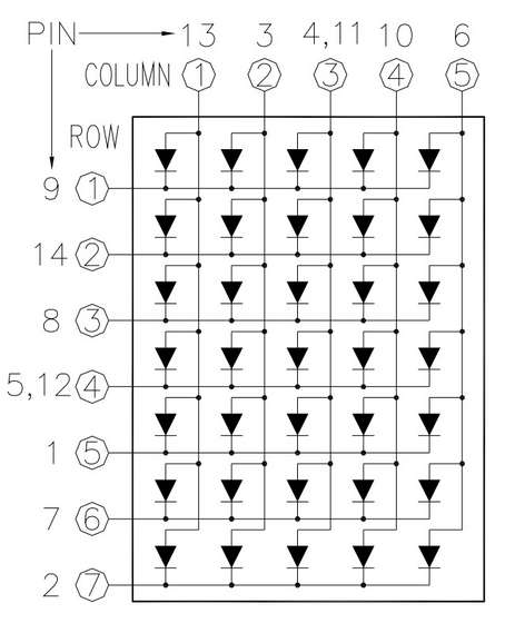
The microcontroller will connect to the LED Array Module using two eight-bit ports. The 5 columns are connected to 5 lines from port A of the microcontroller. The 7 rows will be connected to 7 lines from port C.
The 5 column lines correspond to port A bits b0 to b4. Bit b0 is column 1, b4 is column 5. The microcontroller firmware turns on one column at a time, cycling through this hex pattern over and over:
0x01
0x02
0x04
0x08
0x10
The 7 row lines correspond to port C bits b0 to b6. Port C bit b0 is row 1 while b6 is row 7. The microcontroller firmware sends a pattern to the row unique to each column.
To encode the pattern for a column, the character pattern – font if you want to call it that – was drawn out for each ASCII character. Then each column was converted into a hex byte.
Rows 1-4 are b0-b3. This is the lower nibble of the column pattern. Rows 5-7 are b6-b4 – the upper nibble. If you want LED C1 R1 to be on, then the encoded value for the first byte of the character becomes 0x01.
You might note that sending a 0x01 to port C would turn on all of the LEDs in the row except for C1 R1. This is because an on led is encoded as a 1 bit, while the off LEDs are encoded as 0 bits. The firmware simply inverts the encoded patterns before sending them to Port C.
It is simpler to understand the patterns when 1 = on.
Step 3 Pattern guide
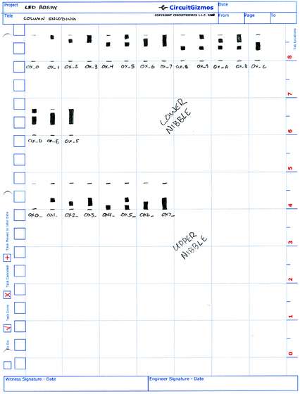
This is a page from my notes. It shows a column from the LED Array Module. A penciled-in square represents an LED that is on. Immediately under it is the hex value for that nibble.
If these LEDs are on:
C1 R1
C1 R3
C1 R5
C1 R7
Then the lower nibble and the upper nibble pattern would translate into the hex value of 0x55.
Each character has 5 columns, so there would be 5 bytes of data needed to display any one character.
Since we are talking about 5 here, the bytes needed to display the 5 character are:
0x27
0x45
0x45
0x45
0x37
This was determined by drawing out the five in a 5 by 7 grid of boxes and encoding each column into a number.
See note1.zip for a copy of the notes.
Step 4 Creating a font for the display
To make a font for the 5 by 7 characters, I filled in a 5 by 7 grid in my notes.
After a while – about the time I got to the ampersand – my hand cramped up from coloring in little boxes. Coloring is the type of thing you want to have a kid do.
Luckily for me about a decade and a half ago I decided to have a kid just to do things like this for me.
So I had my son create this font. In the pictures below are my notes – and by “my” I mean his – that show all of the character patterns as well as the encoded bytes needed to display each column of the character.
See note2.zip for a copy of the notes.
For more Detail: How to use an LED Array Module using AVR


