Summary of PC Controlled Robot using ATmega32
This article outlines building a simple PC-controlled robot using an xBoard v2.0, two DC gear motors, and an RS232 serial link via RealTerm software. The robot features five commands: forward, backward, left, right, and stop. Hardware includes a metal chassis with a castor wheel, while firmware is loaded onto the ATmega32 CPU.
Parts used in the PC Controlled Robot:
- xBoard v2.0
- ATmega32 Main CPU
- CP2102 USB to UART module
- Two 200RPM DC Gear motors
- HQ Metal Chassis
- Front castor wheel
- Plastic wheels
- USB AVR Programmer
- RealTerm terminal software
In this tutorial we will discuss a simple PC controlled robot. The Robot PC link will be a RS232 serial line. The robot will have only five commands.
- Move forward (RS232 char ‘F’ or ‘f’)
- Move backward (RS232 char ‘B’ or ‘b’)
- Turn Left (RS232 char ‘L’ or ‘l’)
- Turn Right (RS232 char ‘R’ or ‘r’)
- Stop (RS232 char ‘S’ or ‘s’)
To keep things as simple as possible, in this example we will use terminal software RealTerm for sending commands to the robot. Later on a dedicated software can be written on PC end to control the robot.
The Robot’s Hardware
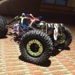
The robot’s hardware will be a simple differential drive using two 200RPM DC Gear motor mounted on a HQ Metal Chassis with a front castor wheel. On the back motors we have mounted plastic wheels. More about differential drive is explained in this tutorial.
The Electronics
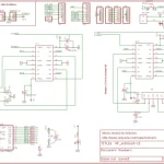
The robot is controlled using xBoard v2.0 which has ATmega32 as main CPU and integrated motor drivers. We have connected xBoard v2.0 with PC using a CP2102 USB to UART module.

Connect right motor to MOTOR-A Connector and left motor to MOTOR-B.
Download and Burn the Firmware HEX file
Download the firmware hex file from the link given below and program it to the xBoard v2.0 using a USB AVR Programmer. Make sure the fuse bits are set as follows :-
HIGH Fuse = 0xC9
LOW Fuse =0xFF
CP2102 Module Connection

Connect one side of CP2102 module to USB and other side to xBoard v2.0 as listed below.
| xBoard v2.0 | CP2102 Module |
| RxD | TxD |
| TxD | RxD |
| GND | Gnd |
other pins of CP2102 are unused.
Notes:
- Make sure that CP2102 drivers are installed.
- Jumper JP4 is in Off position (non white side)
- Jumper JP2 and JP3 are in On position (white side)
Finding the COM port number of CP2102 module.
A PC can have several COM ports, each may have some peripheral connected to it like a Modem. Serial Ports on PC are numbered like COM1, COM2 … COMn etc. You first need to figure out in which COM port you have connected the AVR. Only after you have a correct COM port number you can communicate with the AVR using tools such as Hyperterminal. The steps below shows how to get COM port number in case of Virtual COM Ports.
Right Click on “My Computer” icon in Windows Desktop.
For more detail: PC Controlled Robot using ATmega32
-
What are the five commands for the robot?
The robot accepts Move forward, Move backward, Turn Left, Turn Right, and Stop. -
How do you connect the motors to the board?
Connect the right motor to MOTOR-A and the left motor to MOTOR-B. -
Which fuse bits must be set for the firmware?
The HIGH Fuse should be 0xC9 and the LOW Fuse should be 0xFF. -
How are the CP2102 module pins connected to the xBoard?
RxD connects to TxD, TxD connects to RxD, and GND connects to Gnd. -
Where should Jumper JP4 be positioned?
Jumper JP4 must be in the Off position on the non-white side. -
Where should Jumpers JP2 and JP3 be positioned?
Jumpers JP2 and JP3 must be in the On position on the white side. -
What software is used to send commands initially?
Terminal software named RealTerm is used to send commands to the robot.