
Summary of USB POWERED INDUCTANCE METER CIRCUIT ATMEGA8
This article describes a USB-powered inductance meter circuit built around the Atmega8 microcontroller. The device measures coil inductance and displays the frequency and value on an HD44780 LCD screen. It draws power directly from a computer's USB port or an external adapter. The project includes Eagle PCB diagrams, circuit schematics, source code, and hex files for implementation.
Parts used in the USB Powered Inductance Meter:
- Atmega8 microcontroller
- LCD HD44780 driver
- USB port (power supply)
- External adapter (optional power supply)
- Eagle PCB board
- Circuit diagram drawings
- ATMega8 source code
- Hex code file
Coil measurement “Inductance Meter” circuit based on Atmega8 microcontroller LCD HD44780 driver and the system’s power supply is taken from the USB port on the computer or adapter operated with the circuit. Circuit of… Electronics Projects, USB Powered Inductance Meter Circuit Atmega8 “atmega8 projects, avr project, microcontroller projects, “
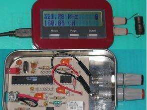
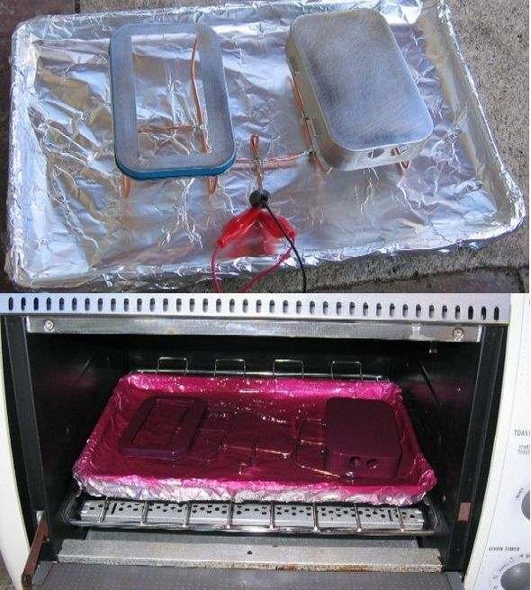
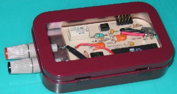
Coil measurement “Inductance Meter” circuit based on Atmega8 microcontroller LCD HD44780 driver and the system’s power supply is taken from the USB port on the computer or adapter operated with the circuit. Circuit of the box mints box cut and processed interesting metal, enamel paint made circuit optimized 🙂
The LCD screen of the circuit 10MHz frequency coil over strut value is displayed in the Information, as well as the frequency.
Coil measurement circuit’s eagle pcb, diagram drawings are ATMega8 source and hex code.
Source: http://rototron.info/ alternative link: usb-powered-inductance-meter-circuit-atmega8.rar
- How is the system powered?
The system's power supply is taken from the USB port on the computer or an adapter operated with the circuit. - What microcontroller is used in this circuit?
The circuit is based on the Atmega8 microcontroller. - What type of display does the device use?
The device uses an LCD screen with an HD44780 driver. - What information is displayed on the LCD screen?
The LCD displays the coil value over a 10MHz frequency strut and the frequency itself. - Can I obtain the PCB design files?
Yes, the article mentions that the coil measurement circuit's eagle pcb and diagram drawings are available. - Where can I find the source code and hex file?
The ATMega8 source and hex code are included as part of the project materials. - Is this project suitable for AVR enthusiasts?
Yes, it is listed under categories including avr project and microcontroller projects. - What is the maximum frequency range mentioned for the coil measurement?
The text specifies that the LCD screen displays values for a 10MHz frequency coil.
