
Summary of 0-30V 0-3A ADJUSTABLE SWITCHING LABORATORY POWER SUPPLY
Summary: A 0–30V, 0–3A laboratory switching power supply based on the LT1074 step-down regulator combines a transformer, switching stage, and a linear post-regulator for improved output quality. It supports inputs up to 60V (HV) and operates at about 100 kHz. Output voltage and current are measured and controlled by an ATmega644 microcontroller. The LT6105-based current-sensing approach uses a low-value precision resistor (e.g., 0.01 Ω) and a differential amplifier to reduce power loss from sensing.
Parts used in the 0-30V 0-3A Adjustable Switching Laboratory Power Supply:
- LT1074 switching step-down regulator
- LT6105 (current-sense amplifier)
- ATmega644 microcontroller
- Precision current-sense resistor (example 0.01 Ω)
- Transformer (for input supply)
- Linear post-regulator stage
- Inductor for switching regulator
- Schottky diode or switching diode
- Input and output capacitors (electrolytic/ceramic)
- Resistors and potentiometers for adjustment
- PCB and connector hardware
DC-DC Laboratory Power Supply 0-30V 0-3A LT1074 is a switching regulator type step-down (lowering) with a maximum current of 5 A. Can work with the value of the input voltage up to 60 V… Electronics Projects,0-30V 0-3A Adjustable Switching Laboratory Power Supply “avr project, dc dc converter circuit, microcontroller projects, power electronic projects, power supply circuit, power supply project, “
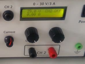
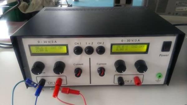
DC-DC Laboratory Power Supply 0-30V 0-3A LT1074 is a switching regulator type step-down (lowering) with a maximum current of 5 A. Can work with the value of the input voltage up to 60 V version (HV) and the output voltage can be set in the range of 2.5 V – 50 In. Without modifying the circuit works the circuit with a frequency of 100 kHz.
LABORATORY POWER SUPPLY CIRCUIT SCHEMATIC
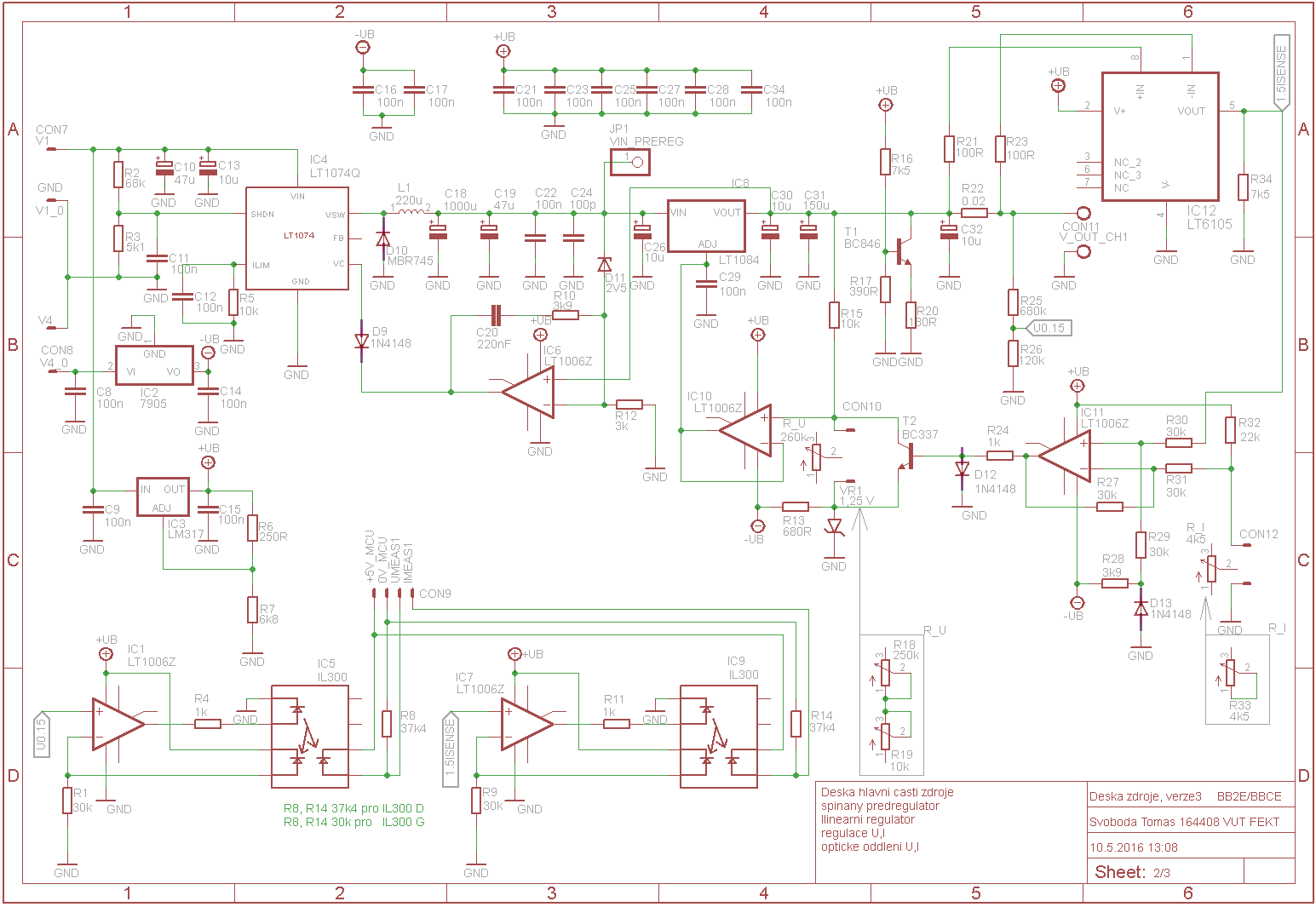
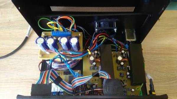
The stabilized power supply with a controllable output voltage 0 – 30 V and a controllable current limitation 0 – 3 And. The source combines the use of the transformer. The switching regulator and the subsequent application of a linear regulator for better output characteristics. Implemented is also a measurement of the output voltage and current of the microcontroller, atmega644.
LT6105
The use of this circuit replaces the need to scan the current on the sensing resistor of the normal value (often 1 Ω), on which arises a large voltage drop and thus a large power loss including an increase in the internal resistance of the source. When using this circuit is the current sensed by the differential amplifier to the precision resistor of small value (for example, 0.01 Ω), which can be connected in any branch of the sources. Since this resistance value is small, there arises in him even a small power loss (given by the product of the resistance and the squared current).
Source: 0-30V 0-3A ADJUSTABLE SWITCHING LABORATORY POWER SUPPLY
0-30v switchmode lab power supply circuit pcb schematic all files alternative links: 0-30v-0-3a-adjustable-switching-laboratory-power-supply.rar alternative link2
- What regulator is used for the main step-down function?
The LT1074 switching regulator is used for the main step-down function. - What is the adjustable output voltage range?
The output voltage can be set in the range 0–30 V for this lab supply; the LT1074 HV version supports up to 50 V or 2.5–50 V as noted. - What is the adjustable current limit range?
The current limitation is adjustable from 0 to 3 A. - What microcontroller is used for measurement and control?
The ATmega644 microcontroller is used to measure and control output voltage and current. - How is current sensing implemented to reduce power loss?
Current is sensed by a differential amplifier (LT6105) across a small-value precision resistor (for example 0.01 Ω) to minimize voltage drop and power loss. - What maximum input voltage can the circuit handle?
The design can work with input voltage up to 60 V in the HV version. - What switching frequency does the circuit operate at?
The unmodified circuit operates at around 100 kHz. - Is a transformer used in the source design?
Yes, the source combines the use of a transformer with the switching regulator and linear regulator stages. - Why is a linear regulator used after the switching stage?
A linear post-regulator is applied for better output characteristics after the switching stage. - Are PCB and schematic files available for the project?
Yes, PCB and schematic files are referenced and available as archived downloads (example rar files).
