
Summary of ATmega8 Based Multi channel IR Remote
This article describes a 5-channel IR remote control system using an ATmega8 microcontroller and NEC protocol. It allows users to map specific remote keys to five loads (up to AC 220V, 6 Amps) via a simple boot-time configuration stored in EEPROM. The system features load status LEDs and operates up to 20 feet away.
Parts used in the Multi channel IR Remote:
- ATmega8 Microcontroller
- NEC Format Remote Control
- Internal EEPROM
- Five Load Indicator LEDs
- Five Power Connectors
- Relays
Today I will present an easy to build Multi channel IR Remote control system. It can control heavy loads (Up to AC 220V 6 Amps or smaller) with a touch of remote control. A total of 5 devices can be controlled from a distance of up to 20 feet. We will be using a standard remote control protocol that is called the NEC format. The NEC format is common in remote controls used with Chinese made CD/DVD players. They are easily available in Indian Markets. They also come in variety of sizes from full to small 21 keys (used in car audio systems).
Our system is smart enough, so the user can set which key controls which load. Their are five load indicator LEDs which provide the state of five loads. When the device is powered on for the first time, the load LEDs start to blink one by one. That is the first load LED starts to blink, this means the system is waiting for the user to assign a key for that load. So you should press the key you want to use for that load. Once the system receives the key of your choice it stores it in internal EEPROM. From now on you can use that key to control that specific load. In this way all five loads are mapped to five keys on the remote control.
The above key mapping procedure is required only once. From the next time the system is started it does not goes through the key mapping procedure. Although if required the same key mapping can be initiated if user wants. This is done by pressing any key on remote control within 3 second of booting. If the system receives any key press during boot up (i.e. within 3 sec. of startup) it starts the key mapper.
Once the key mapping is done, user can switch on/off the loads by just pressing the keys on remote control.
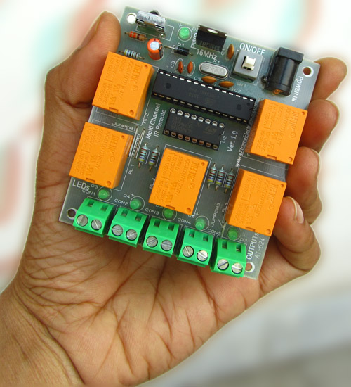
Their are five power connectors (the green thing on the edge of the board), they are used to connect external load. They function like simple switch. That means the two contact are closed (connected) when relay is active. Other wise they are open (NOT connected).
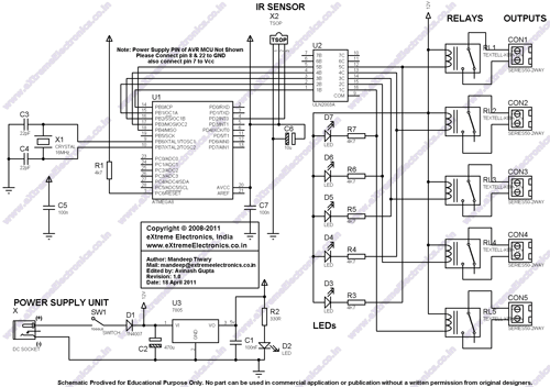
Schematic for Multi channel IR Remote
avr-gcc Source Code for Multi channel IR Remote
/******************************************************************************
 Title:
   ATmega8 Based Multi channel IR Remote.
  Description:
   It can control heady loads
  (Up to AC 220V 6 Amps or smaller)
  with a touch  of remote control.
  A total of 5 devices can be controlled from a distance
   of up to 20 feet. We will be using a standard remote control protocol
   that is called the NEC format. The NEC format is common is remote
   controls used with Chinese made CD/DVD players remote controls.
  They are  easily available in Indian Markets.
  They also come in variety of sizes
   from full to small 21 keys (used in car audio systems)
For more detail: ATmega8 Based Multi channel IR Remote -
What is the maximum distance for controlling devices?
The system can control devices from a distance of up to 20 feet. -
How many devices can be controlled simultaneously?
A total of five devices can be controlled by this system. -
What remote control protocol does the system use?
The system uses the standard NEC format commonly found in Chinese CD/DVD players. -
Can the system handle heavy electrical loads?
Yes, it can control heavy loads up to AC 220V at 6 Amps or smaller. -
How are the remote keys mapped to specific loads?
When powered on, the system blinks LEDs sequentially; pressing a key assigns that button to the corresponding load and stores it in EEPROM. -
How can a user re-initiate the key mapping process?
Pressing any key on the remote within 3 seconds of booting will start the key mapper again. -
What do the five power connectors on the board do?
They connect external loads and function like switches, closing contacts when the relay is active.
